Boost Converter is Operating in Continuous Conduction
The Difference between CCM and DCM Explained
DOWNLOAD PDF

Get valuable resources straight to your inbox - sent out once per month
We value your privacy
Introduction
Flyback converters are often used in switch-mode power supplies for AC/DC and DC/DC conversion, especially for the low-to-mid power range (about 2W to 100W). In this power range, flyback converters offer a very competitive size, cost, and efficiency ratio.
A flyback converter's operation is based on a coupled inductor, which — in addition to aiding in power conversion — also provides isolation between the converter's input and output. Other than that, it has the same basic elements as other switching converter topologies: two switches (MOSFET and diode) and an output capacitor.
A flyback converter has two operation phases, tON and tOFF, which are named after and controlled through the MOSFET's switching states.
During tON, the MOSFET is on and current flows from the input through the primary inductor, linearly charging the coupled inductor and creating a magnetic field around it (see Figure 1.b). In the secondary side, the rectifier diode is reverse-biased, disconnecting the transformer from the output (see Figure 1.a).
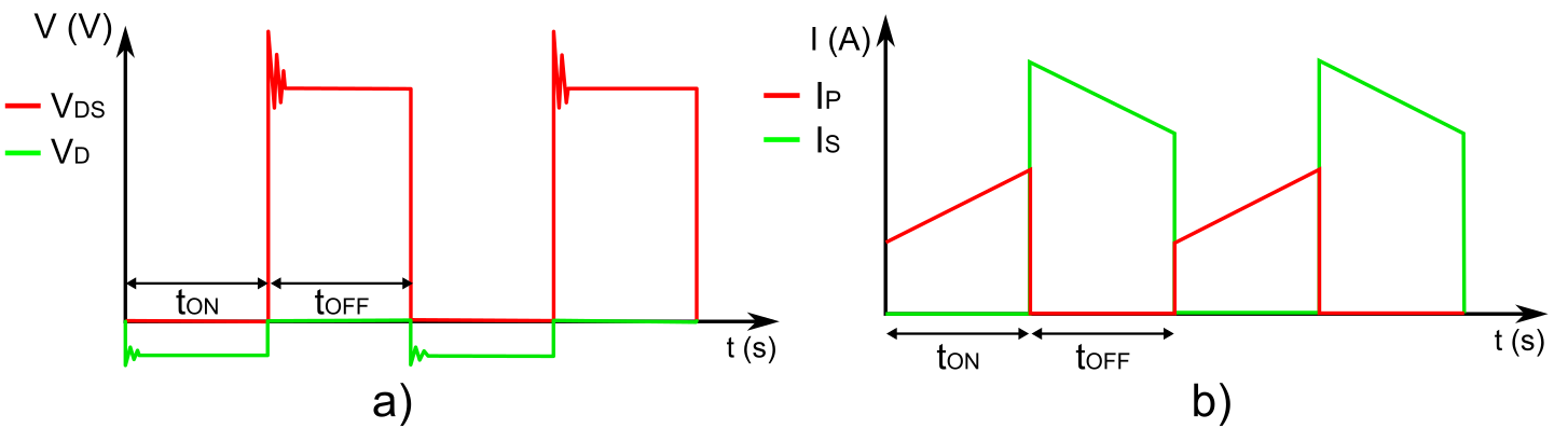
Figure 1: a) Voltage in MOSFET and Diode b) Current in Primary and Secondary Coils
The charge stored in the output capacitor is responsible for maintaining a stable voltage at the load (see Figure 2).
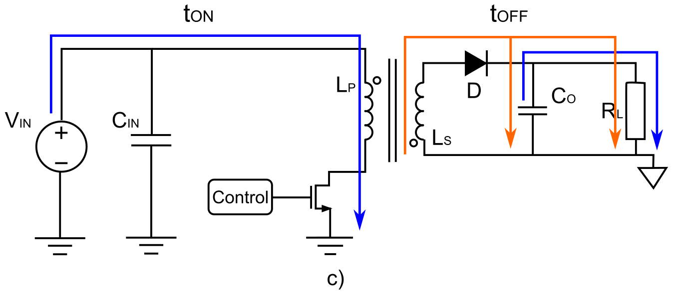
Figure 2: Flyback Converter Current Diagram
During tOFF, the MOSFET is open and the coupled inductor begins to demagnetize through the diode, which is now directly polarized. The current from the inductor then charges the output capacitor and powers the load.
Flyback converter operation can be divided into two modes, depending on the minimum value of the inductor current in each cycle. If the MOSFET switches from tOFF to tON before the inductor is completely discharged, then the current in the inductor is never zero. This operation is called continuous conduction mode (CCM). Alternately, if tOFF lasts long enough for the primary inductor to completely discharge, then there is a period of time during which the current in the inductor is zero. This causes both the diode and the MOSFET to be in an off state, and is called discontinuous conduction mode (DCM).
CCM vs. DCM
A flyback converter's two operation modes seem very similar, but each has its own set of advantages and drawbacks. It is very important for designers to consider these advantages and drawbacks during the design process, as the selected operation mode has significant effects on the efficiency, transformer, regulation, EMI, and cost of the power converter. Figure 3 and Figure 4 show the differences between CCM and DCM operation.
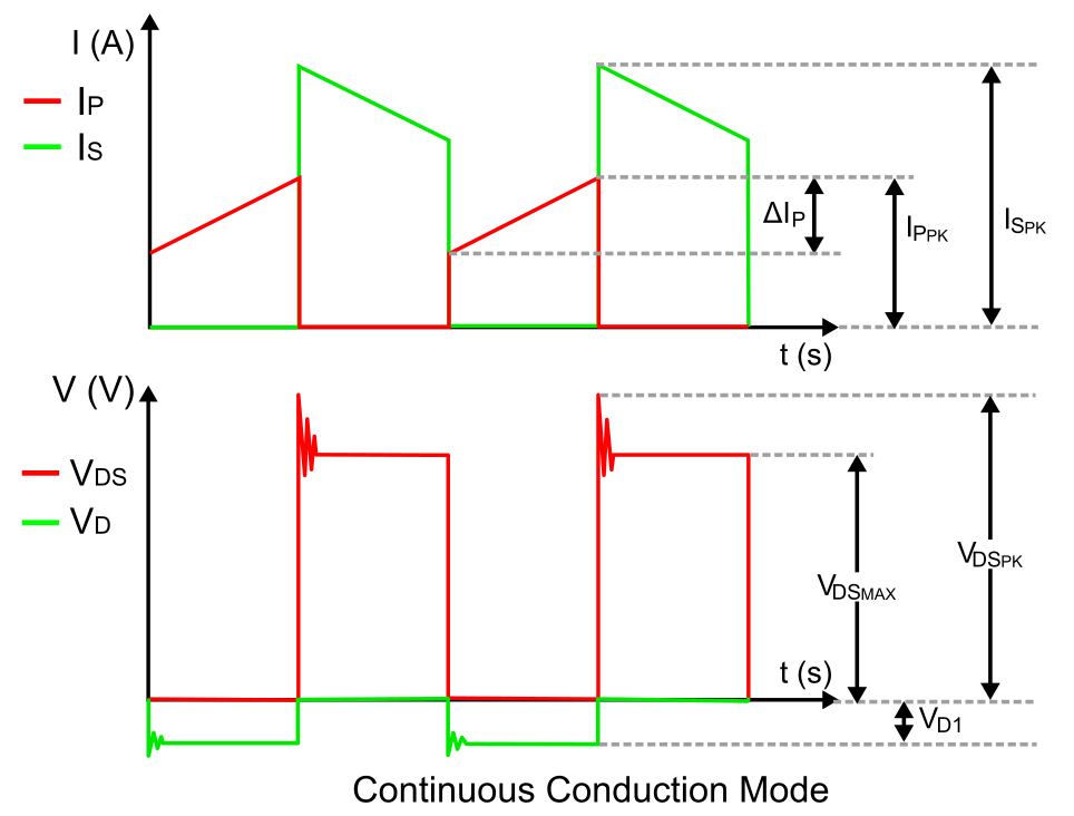
Figure 3: Current and Voltage Waveforms for CCM
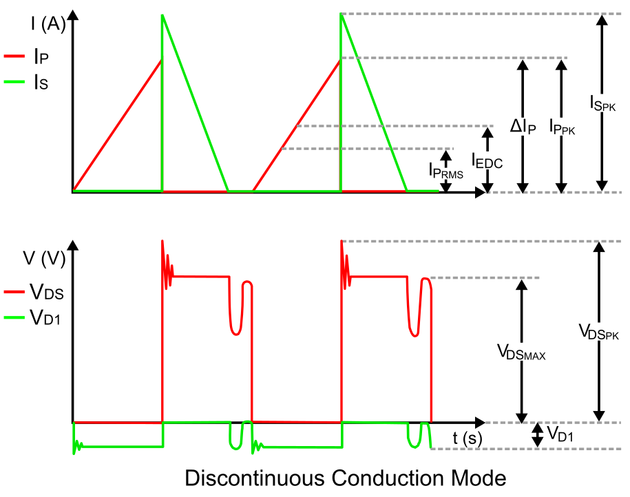
Figure 4: Current and Voltage Waveforms for DCM
Efficiency
DCM offers higher efficiency than CCM, due to the lack of reverse recovery loss on the diode and a softer turn on of the MOSFET. However, if the duty cycle is too small, then the current that charges the primary inductor will be very high, which lowers the converter's overall efficiency. Thus, a reasonable duty cycle must be chosen for DCM to take advantage this benefit.
Transformer
Regarding the transformer size, DCM requires a smaller inductance, which theoretically means it can use a smaller transformer. However, due to the incremented spikes on the primary- and secondary-side currents, the transformer wire gauges must be larger, which means in both cases the transformers would be more or less the same size. Despite this, DCM does actually allow for a smaller transformer; because it is more efficient than CCM, the switching frequency in DCM can be increased, allowing for the implementation of a smaller transformer.
Regulation
Regarding regulation and stability of the system, a flyback in DCM is easier to compensate than a flyback in CCM. This is because the problematic right-hand plane zero (RHPZ) appears and introduces instability at lower frequencies when the converter operates in CCM. DCM pushes the RHPZ to higher frequencies, making the loop easier to compensate, and therefore offering faster transient response than CCM.
Furthermore, when working with duty cycles above 0.5, subharmonic oscillation may occur in CCM flyback converters, which means slope compensation is required.
EMI
Because DCM charges and discharges the inductor completely, the primary current ripple is logically much greater than in CCM. This current ripple generates a variating signal, which is then propagated due to the antenna-like behavior of the different components in the primary current loop, generating significant levels of electromagnetic interference (EMI).
On the other hand, DCM flyback converters also implement zero-current switching (ZCS), which makes it more energy-efficient, as it reduces the rectifier diode's reverse recovery. This soft switching affects efficiency and has a strong effect on EMI, because the fast-recovery diodes that must be used in order to reduce energy loss also generate very sharp voltage spikes in the secondary side, which cause ringing and can be a source for high-frequency differential-mode noise. To solve this, a snubbing circuit must be implemented to reduce these peaks and ensure compliance with electromagnetic compatibility (EMC) standards and regulations.
Summary
This article offered an introduction to the main differences between continuous conduction mode (CCM) and discontinuous conduction mode (DCM). Table 1 shows a summary of these differences, as well as an outline of the differences not mentioned above.
| Variable | DCM | CCM |
| Efficiency | Higher | Lower |
| MOSFET VDS_MAX | Same | |
| MOSFET ID_MAX (IP_MAX) | Higher | Lower |
| Rectifier Diode Reverse Voltage Peak (VD_PK) | Same | |
| Rectifier Diode Current Peak ID1_PK (IS_PK) | Higher | Lower |
| RMS Current and Ripple | Higher | Smaller |
| Transformer Size | Smaller | Larger |
| EMI | Higher, requires larger capacitors and filters | Lower, smaller capacitors and filters |
| Cross-Regulation | Higher variation | Lower variation |
| Transient Response | Faster | Slower |
| Stability |
|
|
Table 1: DCM vs. CCM
MPS offers a large variety of flyback converters that can operate in both operation modes, as well as reference designs, tools, webinars, and other articles that help you understand the theory behind flyback converter design, speed up the design and component selection process, and avoid any unexpected behavior in your circuit. To learn more, explore our flyback solutions and our Flyback Design Tool.
_______________________
Did you find this interesting? Get valuable resources straight to your inbox - sent out once per month!
Technical Forum
Get technical support
gillespiearans1986.blogspot.com
Source: https://www.monolithicpower.com/en/the-difference-between-ccm-and-dcm-explained
0 Response to "Boost Converter is Operating in Continuous Conduction"
Kommentar veröffentlichen